Restpresso, a REST powered Espresso maker
[ ]
]
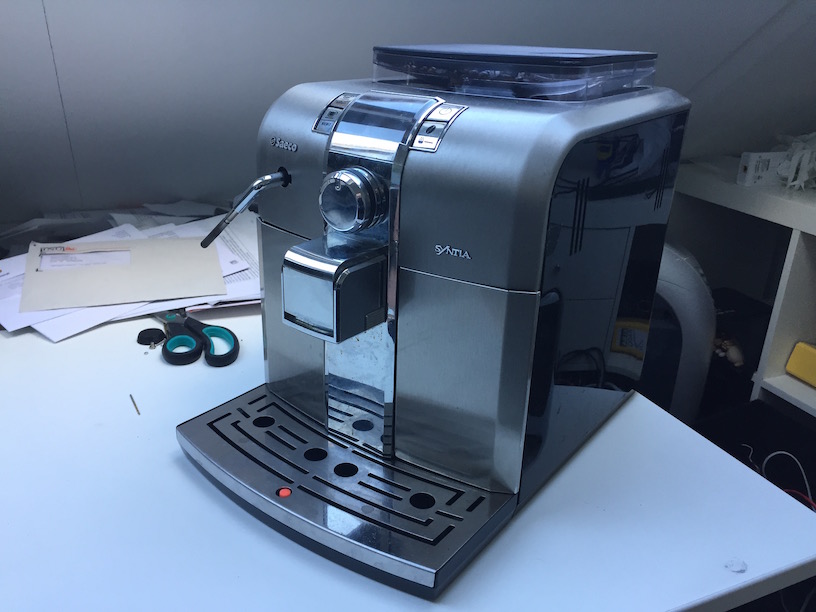
My friends over at Sanoma organised a small hackathon last week, and asked me if I wanted to join. I looked at my bucketlist of projects, and saw my espresso machine gathering dust, so an idea was born. Why not create a wifi enabled Espresso machine, which you can remotely command to pour you a coffee.
By popular demand, watch the video!
[ ]
]
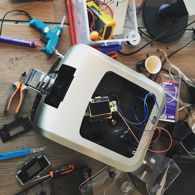
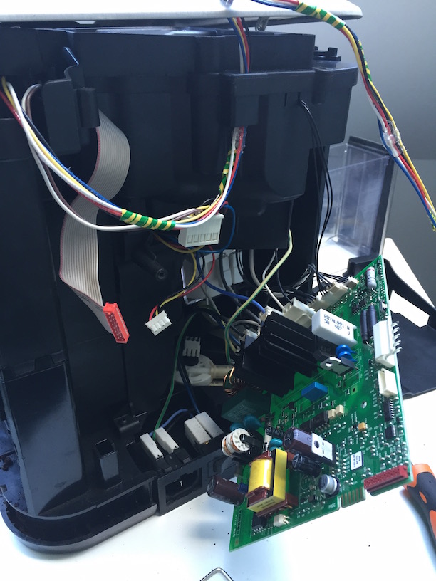
I had a vague idea of what the machine would look like on the inside, but didn’t bother to check it before the hackaton (oops). Ofcourse I brought my whole collection of screwdrivers, except for the tiny torques screws that it uses (ugh), but fortunately, somebody else at the event brought them along, so no worries there :)
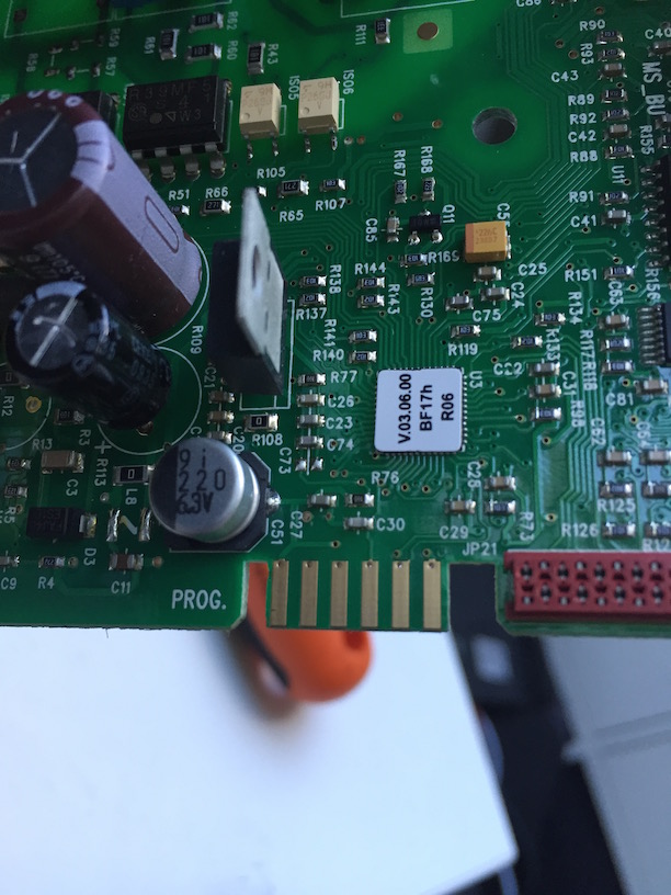
Once opened, I found out that there actually is a debug/programmer port, it looks like a simple jtag/debugging port. But that was out of scope for today. I wanted to see if we could simply hotwire the wires onto the buttons. Ofcourse, for that, I had to almost take the whole machine apart…
[ ]
]
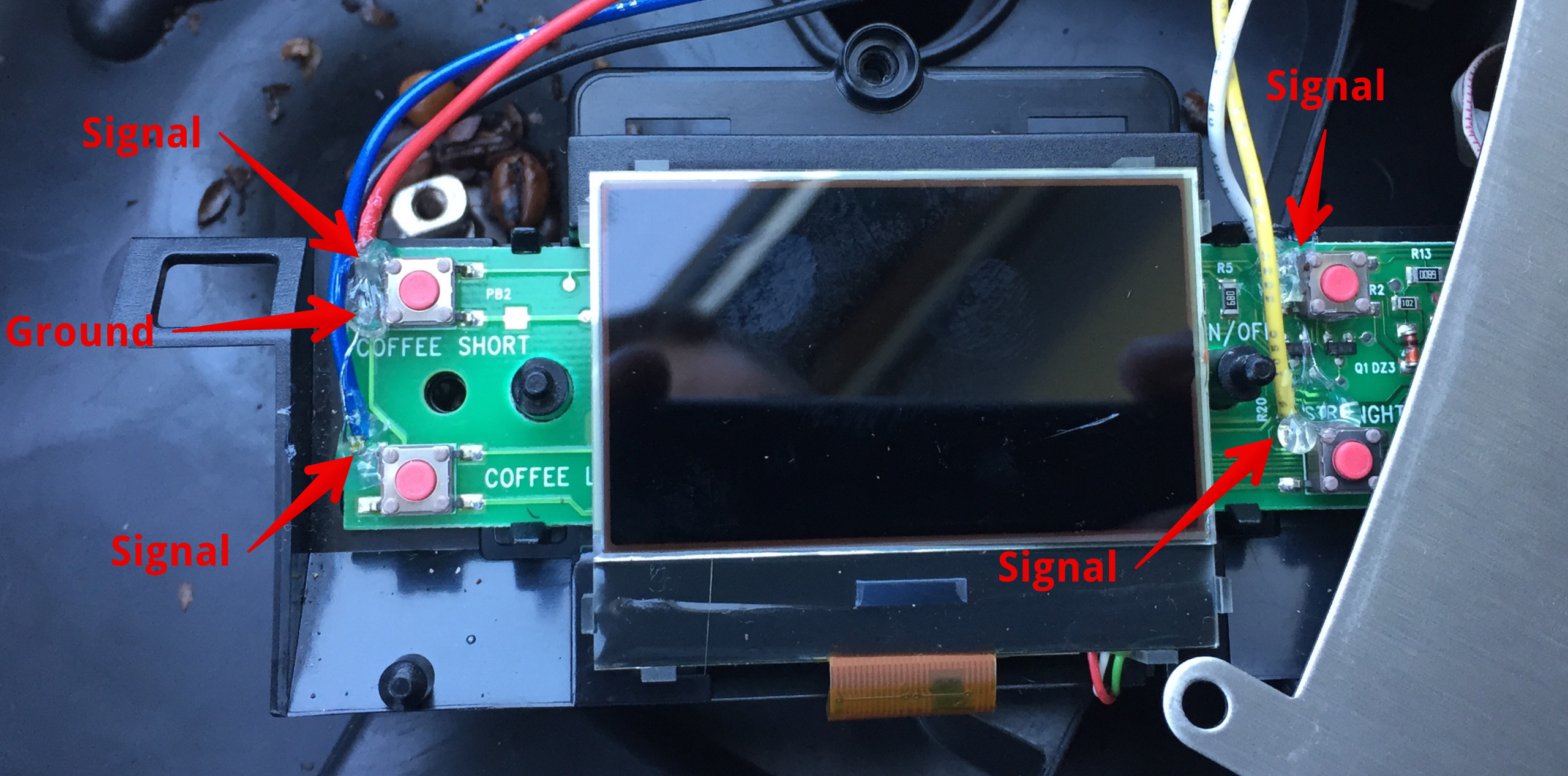
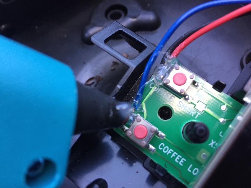
Once I finally could reach the push buttons, I could just measure the correct pins, solder a ground pin, and some signal wires onto those ports, and close everything up.
So how does this work?
The way this “hack” works, is basically that we will be ‘short circuiting’ the push buttons. When you physically push the button, a connection is made between the ground pin, and the signal pins. On those pins, I just soldered some extra wires. On the Raspberry Pi, when we make the GPIO port -low- in our software (eg: 0, not 1), you actually just connect it to ground (“Pulling it to ground”), which will trigger the software in the Espresso machine, just as if you were pressing the button.
You can do this “hack” on any device that has these kinds of push pins. You just need to find which pin they trigger, and whether they are pulled to ground (0) or high (1).
It’s pretty simple to find out which is which. Find a ground pin somewhere (a dead giveaway, sometimes they actually say ‘ground’ or ‘gnd’ on silkscreen on the pcb. Usually all the push buttons will share a ground (a common ground). That’s pretty easy to find: use either the signalling function on your multimeter (the ‘beeping’ thing), or check the ohm meter (if it’s near 0 or 0, there probably is a connection). In this way, systematically loop through all pins, while you keep one of the measuring pens on the same pin all the time. Once you find a connection, you’ve find the ground pin, the other pin is the ‘signal’ pin. You can check by switching the pins, and pushing the button, if a connection is made, you’ve found both pins.
So now we hotwired all the buttons. We can get the machine out of standby (or bring it into standby), adjust the amount of milled beans, pour a cup of regular coffee, or pour an espresso, right from the Raspberry Pi.
[ ]
]
I glued all the solder joints with some hot glue, just to be sure. I didn’t want to open the machine all the way back open again because of some poor soldering on my part (booh). There is also a flat flex cable running all the way to back, which I could have used (but didn’t want to bother checking all the pins), I used the plastic clips from the flat flex cable to tug away the extra wires all the way to the back.
Pro tip: always solder on a longer wire than you think you will need! :)
[ ]
]
While I was soldering like there was no tomorrow, my friend Sjoerd Arendsen was already working on the api part for the project. I wanted to use Flask for the api, but he had more experience with Django Rest Framework, so went for that. We decided on just supporting GET calls for now (boohoo!). You can find the whole source code on Github, but it’s not much.
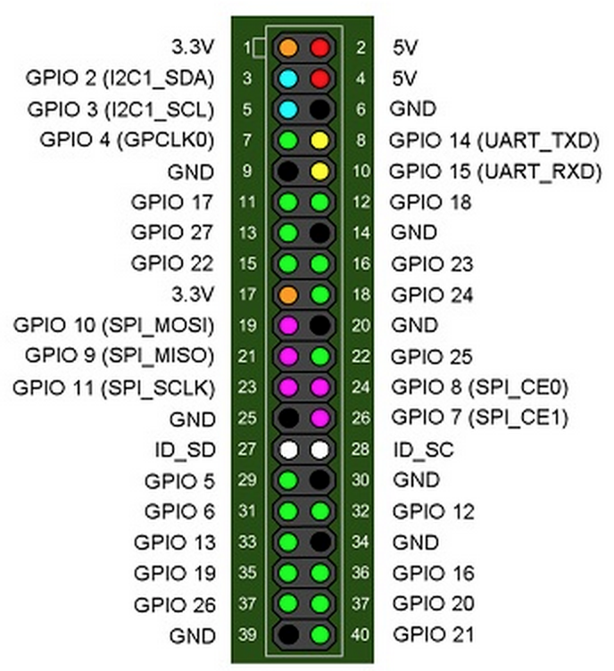
When you connect something to the Raspberry Pi, you can’t just use any gpio port. Some gpio pins actually have a specific function (I2C, SPI, etc) by default, and you should only use or overwrite those if you know what you’re doing. Since we just needed a couple of random ports, we selected some green ports from this diagram (the green ones are free to use).
We had some timing issues with the push buttons, but we got it to work after some debugging (blast! A realtime device like an arduino or other AVR would have helped here).
To trigger one of the buttons, the most basic example in python would be this:
# import the gpio modules
import RPi.GPIO as GPIO
# set the mode to BCM numbering (see the above reference)
GPIO.setmode(GPIO.BCM)
# Toggle pin 17 high
GPIO.output(17, 1)
# Toggle pin 17 low
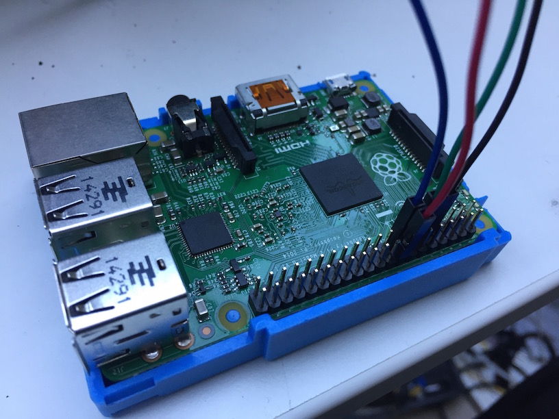
GPIO.output(17, 0)I was looking for a way to hide the RaspberryPi in the machine itself, but unfortunately I couldn’t find a decent power source for it. The RPi needs 5v and about 2 Amps for proper function, and the only thing I could find on the pcb was a 5v 1A voltage regulator. I didn’t bring any usuable power regulators, so we had to keep the RPi on outside, powered by the USB adapter :(
Other ideas
During the day, we came up with some other ideas we didn’t pursue (but would be fun to add):
- Automatic cup dispenser: with a tube, some plastic cups, and a servo, create a little latch which would dispense one cup on the stand.
- Add a webcam so you can see your coffee being brewed
- Auto tweet with a picture of the coffee being brewed
- Add some statistics (and graphs! lots of spiffy graphs!)
- Add mDNS for automatic discovery + Siri
- Solder in a proper power regulator so we can hide the RPi inside the Espresso Machine
Conclusion
We had to build the hack with some time constraints on the day, as we both had other plans for the evening (read: 🍻). The hack ended up being a bit crude, but it works! It was surprisingly easy to solder on the buttons, and get our little hack to work, awesome! ☕️